
Views: 0 Author: Site Editor Publish Time: 2026-09-01 Origin: Site


You should not view the Engine Flywheel as just a basic mechanical disk spinning in the dark. It actually acts as a critical determinant of drivetrain longevity, engine stability, and operator comfort. Every modern combustion engine relies heavily on its kinetic management to function properly. Selecting or specifying this component requires careful planning. Whether you design OEM manufacturing systems, heavy-duty industrial equipment, or performance automotive upgrades, you face similar engineering challenges. You must balance rotational inertia, total assembly weight, and extreme thermal resistance accurately. A wrong choice often leads to harsh vibrations or catastrophic driveline failure. This guide moves well beyond basic introductory physics. We provide a highly practical framework here. You will learn how to evaluate and select the right FlyWheel architecture for specific mechanical applications. We cover everything from material specifications to manufacturing tolerances so you can make informed engineering decisions.
Core Function: An engine flywheel manages kinetic energy, dampens power pulses, and maintains rotational momentum between combustion cycles.
Design Trade-offs: Selecting between single-mass and dual-mass systems requires a direct compromise between durability and NVH (Noise, Vibration, Harshness) reduction.
Material Selection: Performance and scalability depend heavily on material grade (e.g., cast iron vs. billet steel) and machining tolerances.
Lifecycle Costs: Initial procurement costs must be weighed against implementation realities, including clutch compatibility, resurfacing limitations, and failure risks.
Internal combustion engines do not produce power continuously. They generate power in violent, isolated bursts during the combustion stroke. The other mechanical strokes—intake, compression, and exhaust—consume energy rather than produce it. The flywheel bridges this operational gap seamlessly. It acts as a mechanical battery storing kinetic energy. When the crankshaft accelerates during combustion, the metal disk absorbs the rotational force. As the engine moves into the energy-consuming strokes, it releases this stored momentum back into the system. This continuous exchange smooths the erratic delivery of torque from the crankshaft. Instead of violent jerks, the transmission receives a continuous, usable rotational force. Heavier designs store more kinetic energy, making them excellent for maintaining idle stability in large displacement engines.
Combustion events create violent twisting forces. These forces travel directly down the crankshaft as harmonic vibrations. If left unchecked, these torsional spikes cause severe damage. The flywheel functions as a massive structural dampener. It absorbs these harmonic vibrations before they reach delicate downstream components. Without this dampening effect, you would experience accelerated wear on the transmission gears, synchros, and clutch assembly. The sheer mass of the component resists sudden changes in rotational velocity. This resistance prevents microscopic twisting motions in the crankshaft from snapping metal components under heavy load. We rely heavily on this stabilizing force to safeguard the entire driveline architecture.
Beyond kinetic management, this component serves a vital starting function. Manufacturers integrate a hardened steel ring gear around its outer perimeter. This ring gear serves as the primary mechanical engagement point for the starter motor. When you turn the key, the starter motor extends a small pinion gear to mesh tightly onto these outer teeth. The electric motor then physically cranks the heavy engine assembly to life. Once the engine fires and achieves a self-sustaining idle, the starter retracts immediately. The ring gear must endure thousands of these violent engagements over its operational lifespan without shearing or cracking.
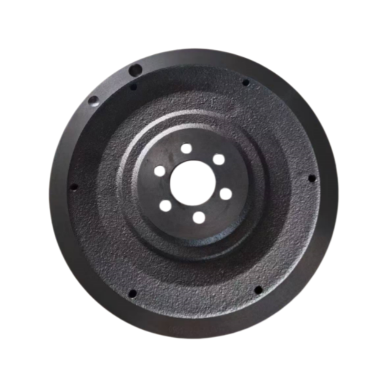
A single-mass setup consists of one solid piece of machined metal. Engineers design them primarily for sheer structural resilience. Heavy-duty commercial applications, demanding motorsport environments, and high-torque industrial machinery rely heavily on them. They contain no internal moving parts, making them incredibly robust under extreme stress.
When evaluating an SMF, you must highlight its exceptional durability. Mechanics can resurface them multiple times, extending their usability significantly. However, you must balance this durability against inherent drawbacks. Solid disks transfer engine pulses directly into the transmission. This transfer increases cabin noise and induces noticeable gearbox chatter at low RPMs. We consider SMFs ideal only when durability heavily outweighs the need for acoustic comfort.
Modern engineering introduced the dual-mass system to solve severe NVH issues. A DMF splits the component into two separate metal masses. A complex internal system of heavy-duty arc springs and planetary gears connects these two sections. One mass bolts to the engine, while the other connects to the transmission. This internal spring network perfectly isolates violent engine pulses.
Modern passenger vehicles and luxury applications require strict NVH control, making DMFs the industry standard. However, you must carefully address their limitations during evaluation. The internal springs have a finite lifespan. Continual heat and extreme torque eventually wear them out. Furthermore, you cannot safely machine or resurface a DMF. Once the friction surface degrades or the springs lose tension, you must replace the entire unit entirely.
Performance builders often debate the merits of component weight. Lightweight billet designs reduce total rotating mass significantly. This reduction frees up parasitic driveline loss. The engine reaches its powerband much faster, resulting in incredibly rapid throttle response. Track-focused cars benefit immensely from this aggressive acceleration characteristic.
Yet, a strict trade-off analysis reveals severe compromises for daily drivability. Lighter metal holds less rotational momentum. You will immediately notice a loss of idle stability. The engine may stall much easier when engaging first gear. Driving up steep inclines becomes difficult because the engine loses its stored kinetic push. Standard mass units retain momentum perfectly, ensuring smooth hill starts and rock-solid idling characteristics.
Drivetrain Component Selection Matrix
Architecture Type | Primary Application | NVH Control | Durability & Maintenance |
|---|---|---|---|
Single-Mass (Standard) | Commercial Trucking, Off-road | Low (Expect gearbox chatter) | Extremely High (Can be resurfaced) |
Dual-Mass | Modern Passenger & Luxury Vehicles | Excellent (Isolates pulses completely) | Moderate (Requires full replacement) |
Lightweight Billet | Motorsport, Track Racing | Very Low (Harsh engagement) | High Structural Strength, Low Momentum |
Nodular and Ductile Cast Iron: Standard automotive and light industrial segments commonly use cast iron. Specifically, nodular iron features graphite flakes suspended in the metal matrix. These flakes absorb vibration naturally. Cast iron remains highly cost-effective while offering a standard thermal capacity sufficient for daily commuting and moderate towing.
Forged and Billet Steel: High-stress applications require vastly superior structural integrity. Billet steel starts as a solid block of metal, machined precisely into shape. The aligned grain structure of forged steel resists shattering under massive rotational forces. When an engine operates at extremely high RPMs or pulls heavy loads, billet steel prevents the component from exploding under stress.
Every time a driver engages the clutch, intense friction occurs between the clutch disc and the metal mating surface. This friction generates massive amounts of heat instantly. The Engine Flywheel acts as a primary heat sink for the entire clutch assembly. It must absorb this thermal energy and dissipate it quickly into the surrounding air.
Evaluating thermal dynamics remains critical. If you select a unit with poor material density, it lacks sufficient thermal capacity. The metal quickly overheats during heavy towing or aggressive shifting. This extreme heat creates hard spots on the friction surface, altering the metallurgical structure into brittle martensite. Eventually, poor thermal management leads to severe warping and premature clutch failure.
You cannot overstate the critical nature of dynamic balancing. Manufacturers must machine these heavy discs to microscopic tolerances. Even a small fraction of a millimeter off-center creates severe operational hazards.
Microscopic imbalances at rest become massive destructive forces at high RPMs. If a heavy metal disk spins out of balance at 6,000 RPM, it acts like an eccentric weight. It violently shakes the crankshaft. This shaking destroys main engine bearings rapidly. It snaps bolts and causes catastrophic drivetrain failure. Elite manufacturers use computerized dynamic balancing machines, drilling precise holes or adding heavy metal weights to ensure perfect rotational symmetry.
Best Practice: Always request computerized dynamic balance testing sheets from the manufacturer before finalizing large procurement orders.
Common Mistake: Never install an unbalanced unit assuming the engine's harmonic balancer will correct the vibration. It will not.
Engineers carefully match the clutch assembly directly to the kinetic profile of the mating surface. You must thoroughly warn mechanics against mixing incompatible components. The most dangerous scenario involves pairing an unsprung, solid clutch disc with a solid, single-mass unit.
The drivetrain requires at least one component to absorb shock. A DMF uses internal springs, so it pairs perfectly with a rigid clutch disc. An SMF has no give, so it demands a sprung-hub clutch disc to absorb the engagement shock. If you combine two solid components, you shift destructive harmonic shocks straight into the fragile transmission input shaft. This oversight routinely shatters gear teeth.
Many traditional mechanics believe they can resurface any solid friction surface endlessly. We must clarify the strict tolerances governing this machining process. Every vehicle platform utilizes a highly specific stack height. Stack height defines the precise distance between the crankshaft mounting flange and the clutch release bearing.
When a machinist removes metal to flatten a warped surface, they alter this crucial stack height. The clutch slave cylinder must overextend to reach the pressure plate. This overextension ruins engagement geometry and causes the clutch to slip. You should follow evidence-oriented guidelines here. Always measure the total material thickness before cutting. If the metal falls below the OEM minimum thickness specification, you must replace the unit rather than resurface it.
Operators and technicians must learn to identify verifiable indicators of metal fatigue early. Ignoring these symptoms leads to roadside breakdowns. You should actively monitor the driveline for the following mechanical warnings:
Clutch Chatter: Experiencing a violent, shuddering sensation during initial engagement in first gear indicates a warped friction surface.
Inconsistent Pedal Feel: A spongy or unpredictable clutch pedal often points to a failing internal spring mechanism inside a dual-mass assembly.
Rotational Play: When inspecting a DMF during a transmission drop, excessive independent movement between the two masses confirms the internal dampeners have collapsed.
Metallic Rattling: Hearing a distinct metallic knocking noise at engine idle strongly suggests the internal planetary gears of a DMF are disintegrating.
Procurement teams cannot rely on guesswork when ordering heavy driveline components. You must clearly define operational success criteria upfront. Advise your engineering team to match the physical specifications strictly to the application's maximum torque output. Analyze the anticipated thermal load generated by the vehicle's specific duty cycle. Furthermore, establish a clear NVH tolerance baseline. A commercial delivery fleet requires durability above all, while luxury sedans demand absolute silence. Aligning these factors guarantees you select the correct architecture.
The global aftermarket contains countless substandard metal castings. Instruct buyers to mandate rigorous compliance metrics during vendor selection. Look exclusively for facilities boasting ISO-certified manufacturing protocols. IATF 16949 certification remains the gold standard for automotive production. Furthermore, demand verifiable dynamic balance testing sheets for every batch. Strict metallurgical sourcing prevents catastrophic failures caused by hidden casting voids or impure iron mixtures.
Before committing to a non-standard specification or upgrading an entire fleet, take deliberate engineering steps. Recommend consulting extensively with certified powertrain engineers or primary OEM suppliers. You should ask them to run software-driven torsional vibration simulations. These digital stress tests reveal precisely how a new weight profile will interact with existing crankshaft harmonics. Taking these actions eliminates trial-and-error, ensuring a safe, reliable final driveline configuration.
Evaluating this critical mechanical component is ultimately an exercise in managing kinetic trade-offs effectively.
Prioritizing upfront durability through solid-mass designs versus demanding operational smoothness through dual-mass systems must align directly with your end-user's application.
Always prioritize raw material integrity, exact metallurgical sourcing, and precise computerized balancing over simple cost savings.
Implement strict inspection protocols to verify stack height tolerances before approving any resurfacing procedures.
Protect your broader powertrain investment by strictly matching compatible clutch friction assemblies to your chosen dampening architecture.
A: Yes, mechanics frequently perform this using an SMF conversion kit. You achieve significantly improved component durability and lower long-term replacement costs. However, you must accept severe trade-offs. You will experience increased gearbox chatter, harsher clutch engagement, and potential long-term transmission wear due to un-dampened harmonic vibrations.
A: Lifespans vary heavily by architecture. Solid, single-mass versions often last the entire lifetime of the vehicle, requiring only occasional resurfacing during clutch swaps. Conversely, dual-mass assemblies experience internal mechanical wear. They typically require full replacement every 80,000 to 100,000 miles, usually concurrently with a standard clutch replacement.
A: No, it does not create horsepower. Lighter mass simply frees up parasitic drivetrain loss by reducing heavy rotational inertia. This allows the engine to rev much faster and reach its peak powerband quicker. However, you sacrifice crucial momentum retention, making idle stabilization and hill starts notably more difficult.
A: Verifiable symptoms include violent shuddering during clutch engagement in first gear, commonly known as clutch chatter. You might notice a strong burning smell from excessive slippage. Additionally, a distinct metallic rattling or knocking noise at idle specifically indicates that the internal springs of a DMF have failed.


